- Flex PCB Blog
- Reflow Soldering PCB Temperature Curve Explanation
- What is FPC
- Special attention points for flexible circuit wiring
- Multilayer PCB Stack-up Basics | PCB Knowledge
- PCB Protection: Potting or Conformal Coating? | PCB Knowledge
- FPCway: Specialized manufacturer of flexible printed circuit boards and rigid-flexible printed circuits
- Future Trends of Flexible Circuit Boards
- Rigid-Flex PCB Stack-up for Impedance Controlled Designs
- Control Impedance Between Rigid PCB and Flex PCB
- Flex PCB Reliability and Bendability
- Normal Flex PCB Specifications
- Flex PCB Polyimide Coverlay and Solder Mask
- Flex PCB Boards and Connectors
- About RA Copper and ED Copper
- Introduction of Flexible PCB
- 5 Tips For Designing Flexible PCB
- Advantages of FPC (Flexible PCB)
- Evolution of the Flex Printed Circuit Board
- Benefits of Using Flex Circuit Boards
- Why Rigid-Flex PCBs are Economical?
- Flexible PCB vs Rigid PCB
- Development of Flexible printed circuit board (FPC) market
- Traditional Manufacture Engineering of FPC Substrate
- Development Trend of FPC Board
- Flex PCB and the Manufacturing
- About Flex PCB design
- About Flex PCB and Assembly
- How to Ensure Flex PCB Design Success
- How to Select the Appropriate FPC Materials?
- The Differences In Rigid PCB, Flex PCB and Rigid-Flex PCB
- Flex-Rigid PCB Design Guidelines
- Beneficials for Polyimide Flex PCB Boards
- About Stiffener on Flex PCB FPC circuit Boards
- About ENIG and ENEPIG
- PCB Surface Finish Comparison
- Copper Thickness for FPC Boards
- Interconnect Solutions for Flexible Printed Circuits and Etched Foil Heaters
- Advantages and Disadvantages of Rigid-Flex PCB
- About FPC Plating Process
- About EMI shield design for Flex Printed Circuit Board
- PCB Assembly Blog
- FPC Research Blog
What is FPC (Flexible Printed Circuit)?
#1 Overview
FPC, also known as flexible printed circuit, is favored due to its lightweight, thin thickness, free bending and folding, and other excellent characteristics. With the rapid development of the electronics industry, circuit board design is increasingly moving towards high precision and high density. Traditional manual inspection methods can no longer meet production needs, and automatic defect detection of FPC has become an inevitable trend in industrial development.
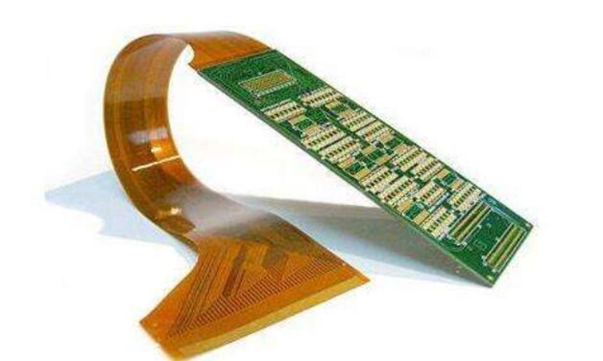
Flexible printed circuit (FPC) is a technology developed by the United States in the 1970s to develop aerospace rocket technology. It is made of polyester film or polyimide as a substrate, with high reliability and good flexibility. By embedding circuit designs on flexible thin plastic sheets, a large number of precision components can be stacked in narrow and limited spaces to form flexible circuits. This circuit can be bent and folded at will, with light weight, small volume, good heat dissipation, and convenient installation, breaking through traditional interconnection technologies. In the structure of flexible circuits, materials include insulating films, conductors, and adhesives. Flexible printed circuits are the only solution that meets the requirements of miniaturization and mobility of electronic products. Flexible printed circuits can greatly reduce the volume and weight of electronic products, making them suitable for the development of electronic products towards high density, miniaturization, and high reliability.
#2 FPC Composite Materials
Insulation Film:
Insulation films form the base layer of the circuit, and adhesives bond the copper foil to the insulation layer. In multi-layer designs, it is bonded to the inner layers. They are also used as protective covers to protect the circuit from dust and moisture and reduce stress during bending. Copper foil forms the conductive layer.
In some flexible circuits, the use of rigid elements made of aluminum or stainless steel can provide dimensional stability, provide physical support for the placement of components and wires, and eliminate stress. Adhesives bond the rigid elements and flexible circuits together. In addition, another material sometimes used in flexible circuits is the bonding layer, which is formed by applying adhesive to both sides of the insulation film. The bonding layer provides environmentally friendly and electrical insulation functions and can eliminate one layer of film, with the ability to bond multiple layers with a small amount of layers.
There are many types of insulation film materials, but the most commonly used are polyimide and polyester materials. Nearly 80% of all flexible circuit manufacturers in the United States use polyimide film materials, and about 20% use polyester film materials. Polyimide materials are non-flammable, geometrically stable, have high tear strength, and withstand welding temperatures. Polyester, also known as polyethylene terephthalate (PET), has physical properties similar to those of polyimide, has a lower dielectric constant, absorbs less moisture, but is not resistant to high temperatures. The melting point of polyester is 250°C, and the glass transition temperature (Tg) is 80°C, which limits their use in applications that require a large number of terminal welds. In low-temperature applications, they exhibit stiffness. However, they are suitable for mobile phones and other products that do not need to be exposed to harsh environments. Polyimide insulation films are usually combined with polyimide or acrylic adhesives, and polyester insulation materials are generally combined with polyester adhesives.
Conductors:
Copper foil is suitable for use in flexible circuits. It can be electroplated (ED) or electroplated. One side of the electroplated copper foil has a glossy surface, while the other side of the processed surface is dull. It is a flexible material that can be made in many thicknesses and widths. The matte surface of ED copper foil is often specially treated to improve its adhesion capacity. Forged copper foil, in addition to being flexible, also has the characteristics of rigidity and smoothness. Suitable for applications requiring dynamic deflection.
Adhesives:
Adhesives not only bond the insulation film to the conductive material but can also serve as a cover layer, as a protective coating, and as a cover coating. The main difference between the two lies in the application method used. The cover layer bonds with the cover insulation film to form a circuit with a laminated structure. Screen printing technology is used for the coverage and coating of adhesives. Not all laminate structures contain adhesives, and laminate structures without adhesives form thinner circuits and greater flexibility. Compared to adhesive-based laminate structures, it has better thermal conductivity. Since the thin structure of the non-adhesive flexible circuit and the elimination of the thermal resistance of the adhesive improve thermal conductivity. It can be used in working environments where adhesive-based laminate structures cannot be used.
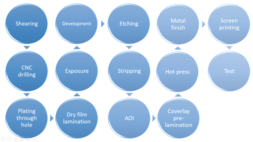
#3 FPC production process
#4 Advantages of Flexible Printed Circuits
Flexible printed circuit boards are printed circuits made of flexible insulating substrates, which have many advantages that rigid printed circuit boards do not have:
Flexible printed circuit boards Can bend freely, coil, fold, can be arranged according to any space layout requirements, and can move and expand in three-dimensional space.
The use of FPC can greatly reduce the volume and weight of electronic products, making them suitable for the development of electronic products towards high density, miniaturization, and high reliability. Therefore, FPC has been widely used in aerospace, military, mobile communication, notebook computers, computer peripherals, pdas, digital cameras and other fields or products.
FPC also has good heat dissipation and weldability, is easy to assemble, and has overall low cost advantages. The combination of soft and hard design also compensates to some extent for the slight lack of component carrying capacity of flexible substrates.
#5 FPC soldering operation steps
Before soldering, apply soldering flux to the pads and treat them with a soldering iron to prevent poor tin plating or oxidation of the pads from causing poor soldering. Chips generally do not require processing.
Use tweezers to carefully place the PQFP chip on the PCB board to avoid damaging the pins. Align it with the pad and ensure that the chip is placed in the correct direction. Adjust the temperature of the soldering iron to above 300 degrees Celsius, apply a small amount of solder to the tip of the soldering iron, press down the aligned chip with a tool, and add a small amount of solder to two diagonal pins. Hold the chip down and solder the pins at the two diagonal positions to secure the chip in place. After soldering the diagonals, recheck the alignment of the chip position. If necessary, adjust or remove and readjust the position on the PCB board.
When starting to solder all the pins, add solder to the tip of the soldering iron and apply soldering flux to all the pins to keep them moist. Touch the end of each pin of the chip with the tip of the soldering iron until you see the solder flowing into the pin. When soldering, the tip of the soldering iron should be parallel to the soldering pin to prevent overlapping due to excessive soldering.
After soldering all the pins, moisten all the pins with flux to clean the solder. Suck up any excess solder to eliminate any shorts or overlaps. Finally, use tweezers to check for misaligned soldering. After checking, remove the solder from the circuit board, soak a stiff brush in alcohol, and carefully wipe along the pin direction until the solder disappears.
SMD resistor-capacitor components are relatively easy to solder. You can first place it on the pad, then place one end of the component on it, use tweezers to hold the component, and then solder one end before checking if it is placed correctly. If it is already aligned, then solder the other end.
Click here for more information:https://fpcway.com/


