- Flex PCB Blog
- PCB Assembly Blog
- FPC Research Blog
- Preparation of FPC based on ultrasonic spraying method_4_Experimental Results
- Preparation of FPC based on ultrasonic spraying method_3_Experimental Procedure
- Preparation of FPC based on ultrasonic spraying method_2_Experimental Platform and Principle
- Preparation of FPC based on ultrasonic spraying method_1_abstract
- Research on Layout Design Method of Ultra-thin FPC_4_Analysis of Layout Design Methods
- Research on Layout Design Method of Ultra-thin FPC_3_Analysis of Layout Design Methods
- Research on Layout Design Method of Ultra-thin FPC_2_Analysis of Layout Design Methods
- Research on Layout Design Method of Ultra-thin FPC_1_introduction
- Research progress on polyimide FPC_2_the field of FPC
- Research progress on polyimide FPC_1_Introduction
- Analysis of Vibration Characteristics of FPCBs _4_Summary
- Analysis of Vibration Characteristics of FPCBs _3_Finite Element Analysis
- Analysis of Vibration Characteristics of FPCBs _2_Theory of Vibration Analysis
- Analysis of Vibration Characteristics of FPCBs Under Random Vibration_1_Introduction
- Design Methods for FPCBs_5_Practical Application
- Design Methods for FPCBs_4_Electrical Circuit Design and Examples
- Design Methods for FPCBs_3_Structure Design Method and Examples
- Design Methods for FPCBs_2_Component Selection Methodology and Examples.
- Research on Design Methods for FPCBs
- Application of MPW technique for FPCBs _4_Summary
- Application of MPW technique for FPCBs_3_Experimental results
- Application of MPW technique for FPCBs_2_Experimental setup
- Application of MPW technique for FPCBs_1_Principle of MPW
- Application of FPCB in PC motherboards_4_ Results and discussion
- Application of FPCB in PC motherboards_3_ Numerical analysis
- Application of FPCB in PC_2_ Experimentation
- Application of FPCB in PC motherboards
- A Bus Planning Algorithm for FPC Design _4_Experimental result
- A Bus Planning Algorithm for FPC Design _3_Proposed Algorithm
- A Bus Planning Algorithm for FPC Design _2_Preliminaries
- A Bus Planning Algorithm for FPC Design _1_Introduction
Preparation of flexible printed circuits based on ultrasonic spraying method_2_Experimental Platform and Principle
1 Experimental Platform and Principle
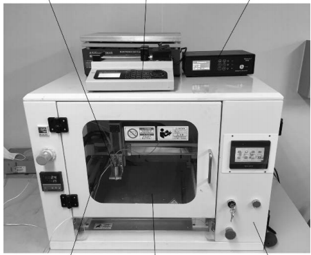
The ultrasonic spraying equipment mainly consists of a liquid supply system, ultrasonic atomization system, motion control system, mechanical system, etc., as shown in Figure 1. It specifically includes an ultrasonic power box, atomizing nozzle, nozzle holder and its motion control system, touch screen control module, adsorption heating platform, and so on.

The ultrasonic atomization system is the key to the ultrasonic spraying equipment, mainly composed of an ultrasonic generator and a transducer vibration system (including ultrasonic atomization piezoelectric transducers and amplitude rods). The ultrasonic generator is used to generate the electrical signals required for the operation of the ultrasonic atomization piezoelectric transducers, which then convert the electrical signals into mechanical vibrations using the inverse piezoelectric effect of piezoelectric ceramics. Due to the constraints of the material and mechanical properties of the piezoelectric transducer itself, the mechanical vibration amplitude at its output end is only a few micrometers, which cannot meet the requirements of processing loads. Therefore, an amplitude rod is added to the output end of the piezoelectric transducer to amplify the mechanical vibration of the transducer. The amplified mechanical vibration amplitude can reach dozens of micrometers, allowing the ultrasonic vibration to act effectively on the acoustic load. For this paper, the acoustic load is the nano silver conductive ink to be atomized.

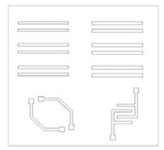
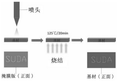
The specific implementation method for preparing FPC is as follows: successively place the substrate (PI film) and metal mask (see Figure 2, overall size is 30 mm × 30 mm, minimum conductive line width is 500 μm) on the substrate placement platform. Set the relevant process parameters on the touch screen according to the required spraying range and the properties of the conductive ink to be sprayed. Perform ultrasonic atomization of the conductive ink, and use the movement of the nozzle holder to drive the nozzle to print precision circuits on the substrate covered with the mask. After completing the coating, sinter the PI film at 125 °C for 20 minutes to complete the preparation of the FPC, as shown in Figure 3.


