- Flex PCB Blog
- PCB Assembly Blog
- FPC Research Blog
- Preparation of FPC based on ultrasonic spraying method_4_Experimental Results
- Preparation of FPC based on ultrasonic spraying method_3_Experimental Procedure
- Preparation of FPC based on ultrasonic spraying method_2_Experimental Platform and Principle
- Preparation of FPC based on ultrasonic spraying method_1_abstract
- Research on Layout Design Method of Ultra-thin FPC_4_Analysis of Layout Design Methods
- Research on Layout Design Method of Ultra-thin FPC_3_Analysis of Layout Design Methods
- Research on Layout Design Method of Ultra-thin FPC_2_Analysis of Layout Design Methods
- Research on Layout Design Method of Ultra-thin FPC_1_introduction
- Research progress on polyimide FPC_2_the field of FPC
- Research progress on polyimide FPC_1_Introduction
- Analysis of Vibration Characteristics of FPCBs _4_Summary
- Analysis of Vibration Characteristics of FPCBs _3_Finite Element Analysis
- Analysis of Vibration Characteristics of FPCBs _2_Theory of Vibration Analysis
- Analysis of Vibration Characteristics of FPCBs Under Random Vibration_1_Introduction
- Design Methods for FPCBs_5_Practical Application
- Design Methods for FPCBs_4_Electrical Circuit Design and Examples
- Design Methods for FPCBs_3_Structure Design Method and Examples
- Design Methods for FPCBs_2_Component Selection Methodology and Examples.
- Research on Design Methods for FPCBs
- Application of MPW technique for FPCBs _4_Summary
- Application of MPW technique for FPCBs_3_Experimental results
- Application of MPW technique for FPCBs_2_Experimental setup
- Application of MPW technique for FPCBs_1_Principle of MPW
- Application of FPCB in PC motherboards_4_ Results and discussion
- Application of FPCB in PC motherboards_3_ Numerical analysis
- Application of FPCB in PC_2_ Experimentation
- Application of FPCB in PC motherboards
- A Bus Planning Algorithm for FPC Design _4_Experimental result
- A Bus Planning Algorithm for FPC Design _3_Proposed Algorithm
- A Bus Planning Algorithm for FPC Design _2_Preliminaries
- A Bus Planning Algorithm for FPC Design _1_Introduction
Design Methods for FPCBs_3_FPCBs Structure Design Method and Examples
After completing the selection of components for the flexible board, the overall structure can be preliminarily planned based on the product wiring relationships and system equipment. This can be done in the following three aspects:
Observe the structural characteristics of the product equipment and make an overall structural plan for the design of the flexible printed board. Identify the available and unavailable areas, and try to avoid the unavailable areas as much as possible.
Understand the wiring relationships of the flexible printed board and clarify the routing requirements between each component. For two related components, try to directly connect them structurally to avoid adding design routing. At the same time, simplify components without wiring relationships to reduce or avoid routing structures.
Further improve the details. For flexible printed boards with a large number of components and complex wiring relationships, consider the design of mounting retention positions to increase product reliability during structural design. At the same time, consider whether rigid areas need to be set up as transfer positions between surface-mount soldering points based on the assembly and soldering methods of the selected components.
During the structural design of the flexible printed board, try to avoid overlapping the component exit positions with other routing positions. This can reduce design difficulty and production costs while improving processability.
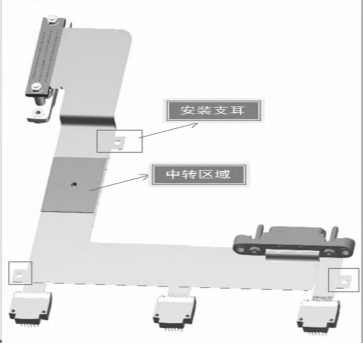
For example, a flexible printed circuit board with five components assembled on a device has a wiring relationship characterized by one component corresponding to multiple components. Most of the component types are J63A straddle surface-mount types with small pin layout dimensions. Based on these characteristics, after observing the positions and spatial structures of various mating devices on the product's supporting equipment, the flexible printed board's component model was selected. At the same time, the structural layout of the flexible printed circuit board began. Since the routing of surface-mount components can only be restricted to one layer, it is necessary to design a transfer area. At the same time, considering the product's structural fixation requirements, the transfer area is used as a fixed area, and additional fixed mounting lugs are added elsewhere. This not only increases the product's reliability but also reduces the number of layers in the electrical circuit design. The final five--terminal flexible printed circuit board structure design is shown in Figure 4.

Figure 4 Structural Design of a Five-Terminal Flexible Printed Circuit Board


