- Flex PCB Blog
- PCB Assembly Blog
- FPC Research Blog
- Preparation of FPC based on ultrasonic spraying method_4_Experimental Results
- Preparation of FPC based on ultrasonic spraying method_3_Experimental Procedure
- Preparation of FPC based on ultrasonic spraying method_2_Experimental Platform and Principle
- Preparation of FPC based on ultrasonic spraying method_1_abstract
- Research on Layout Design Method of Ultra-thin FPC_4_Analysis of Layout Design Methods
- Research on Layout Design Method of Ultra-thin FPC_3_Analysis of Layout Design Methods
- Research on Layout Design Method of Ultra-thin FPC_2_Analysis of Layout Design Methods
- Research on Layout Design Method of Ultra-thin FPC_1_introduction
- Research progress on polyimide FPC_2_the field of FPC
- Research progress on polyimide FPC_1_Introduction
- Analysis of Vibration Characteristics of FPCBs _4_Summary
- Analysis of Vibration Characteristics of FPCBs _3_Finite Element Analysis
- Analysis of Vibration Characteristics of FPCBs _2_Theory of Vibration Analysis
- Analysis of Vibration Characteristics of FPCBs Under Random Vibration_1_Introduction
- Design Methods for FPCBs_5_Practical Application
- Design Methods for FPCBs_4_Electrical Circuit Design and Examples
- Design Methods for FPCBs_3_Structure Design Method and Examples
- Design Methods for FPCBs_2_Component Selection Methodology and Examples.
- Research on Design Methods for FPCBs
- Application of MPW technique for FPCBs _4_Summary
- Application of MPW technique for FPCBs_3_Experimental results
- Application of MPW technique for FPCBs_2_Experimental setup
- Application of MPW technique for FPCBs_1_Principle of MPW
- Application of FPCB in PC motherboards_4_ Results and discussion
- Application of FPCB in PC motherboards_3_ Numerical analysis
- Application of FPCB in PC_2_ Experimentation
- Application of FPCB in PC motherboards
- A Bus Planning Algorithm for FPC Design _4_Experimental result
- A Bus Planning Algorithm for FPC Design _3_Proposed Algorithm
- A Bus Planning Algorithm for FPC Design _2_Preliminaries
- A Bus Planning Algorithm for FPC Design _1_Introduction
Design Methods for Flexible FPCBs_2_Component Selection Methodology and Examples
Selection of locking methods: Based on the components at the user's equipment end, choose the corresponding locking method to meet the locking requirements as much as possible. This can prevent problems such as disconnection and signal interruption during the use of flexible printed boards.
Selection of assembly methods: Consider the space structure of the equipment system when choosing the assembly method and direction of connectors and printed boards, and determine them based on the wiring relationships. Examples include straight-plug printed board style, bent-plug printed board style, straddle-mount style, and surface-mount style.Priority should be given to the later stage printed board design, and through-hole soldering is generally the preferred method.Compared to surface-mount soldering, through-hole soldering can ensure the reliability of the product after soldering.
Selection of pin layout: There are various pin layouts for components, such as the J30J connector, which comes in N-type (straight-plug, with a pin spacing of 2.54mm x 2.54mm), N-J type (straight-plug, with a pin spacing of 1.27mm x 2.54mm), W-type (bent-plug, with a pin spacing of 2.54mm x 2.54mm), and W-J type (bent-plug, with a pin spacing of 1.27mm x 2.54mm). It is generally preferred to choose components with wider pin layouts, but space considerations should also be taken into account.
The above choices regarding components will ultimately constitute a specific model of component. These components should preferably be of universal models to avoid delays in the design and production cycles caused by modifications.
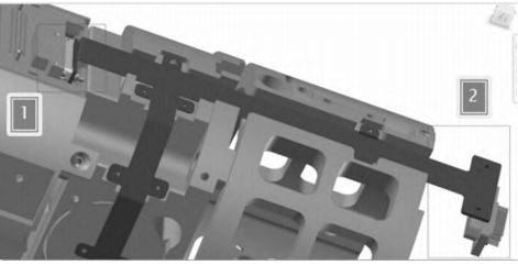
Figure 1 Selection of Scheme 1
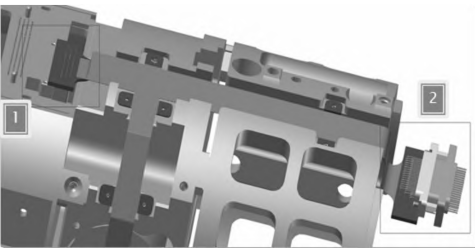
Figure 2 Selection of Scheme 2
Differences in the assembly methods and installation directions of components in flexible boards can affect the structural design and electrical circuit design of the flexible board. As shown in Figures 1 and 2, the comparison results at positions 1 and 2 indicate that Figure 1 uses a straight-plug printed board connector at position 1 and a bottom-surface mount at position 2, while Figure 2 uses a bent-plug connector at position 1 and a surface mount at position 2. Ultimately, the structure and performance of the flexible board will be affected by the connector selection.
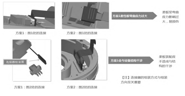
Figure 3 Comparison of Scheme 1 and Scheme 2
As shown in Figure 3, through assembly with the equipment, it can be seen that the selection scheme in Figure 1 has several potential performance hazards. Due to the space limitations at position 1 in Figure 1, which requires bending, using a straight-plug printed board method to assemble components results in the flexible board needing to be bent 90 degrees after assembly and permanently shaped, leading to fatigue damage. The installation surface at position 2 in Figure 1 is determined by the equipment space. Since the mating end on the equipment is located far from the center of the circle, the bottom-surface mounting method is highly likely to cause interference between the flexible printed board and other structures on the equipment, ultimately making assembly impossible.


