- Quick FPC Prototype
- Flex PCB Production
- Rigid-Flex PCB Prototype
- Flex PCB Assembly
- Rigid-Flex PCB Assembly
- Rigid-flex PCB Assembly | FPCway
- Rigid PCB and Assembly
- Electronic PCBA Design
- Components Sourcing
- SMD Stencil
Rigid-flex PCB Assembly Service
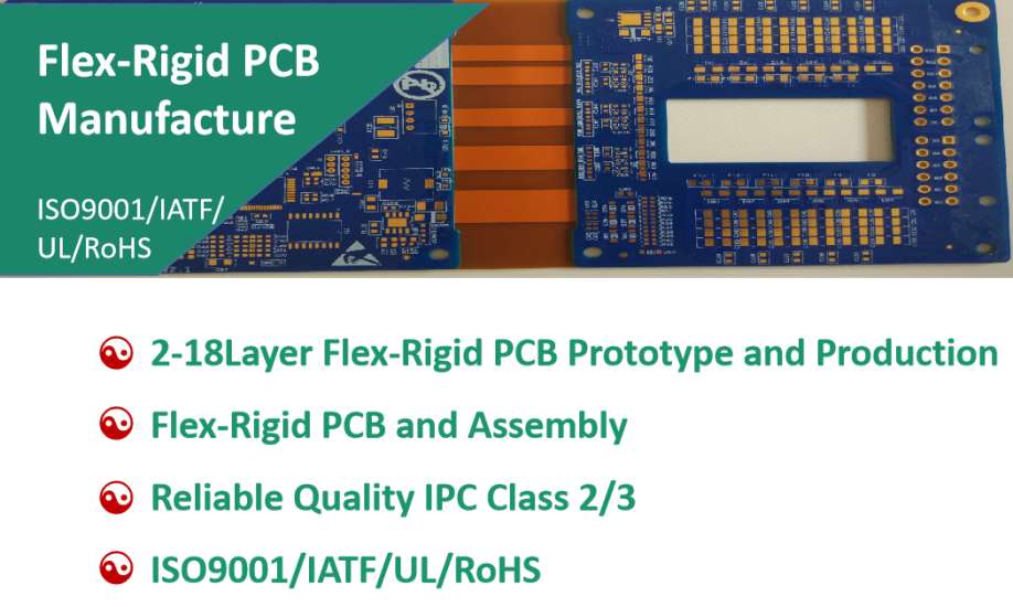
Rigid-flex PCBs are printed circuit boards highlighted by both rigid and flexible areas that make them ideally suited for a wide range of applications. The typical rigid-flex PCB circuit includes two or more conductive layers that comprise either flexible or rigid insulation material between each one - the outer layers may have either exposed pads or covers. Conductors are found on the rigid layers, while plated through-holes are found in both the rigid and flexible layers.
Our excellent Rigid-flex PCB assembly service could do 2-18Layer Rigid-flex PCB Fab and Assembly and components sourcing, no MOQ and no shape/size limit.
The Advantages of Rigid-Flex PCB Technology
While this type of rigid-flexible circuit may be more expensive to design and produce, it does offer a number of important advantages. For instance, the reduced size makes it easier to fit more components into a smaller space. This can actually help to lower overall system costs. Additionally, because they require the need for fewer interconnects and related parts and components, these flexible circuit board can also prove to be more reliable and require less maintenance in the long run.
As with all types of flexible circuit boards, the rigid-flex printed circuit boards will perform well in even the harshest environments, especially those featuring extreme heat. A rigid-flex board is also easy to test, making it well-suited for prototyping.
Rigid-Flex PCB Assembly Process and Capabilities
Rigid-Flex PCB Assembly Process | Rigid-Flex PCB Assembly Capabilities | Rigid-Flex PCB Assembly Machines |
Material Receiving → IQC → Stencil & Assembly Fixture → SMT Line Loading → IPQC → Solder Paste Printing → QC → Automatic SMD Mount → QC → Reflow Soldering → QC → AOI → SMT QC Sampling (QA) →
DIP Line Loading → IPQC → DIP Assembly → Wave Soldering → Touch Up → QC → DIP QC Sampling (QA) → Functional Circuit Test (FCT) → FCT QC Sampling → Packing → Shipping | Max Board Size: 250mm*610mm | GKG Automatic Solder Paste Printers |
SMT & Thru-hole & Hybrid Assembly | Panasonic High-speed SMT Machines Yamaha Multi-functional SMT Machines | |
01005, 0201, BGA 0.3mm pitch, QFP 0.3mm pitch | Reflow Oven & 1 Wave Soldering Oven | |
Lead-free - RoHS | AOI (Auto Optical Inspection) Machines | |
Visual Inspection, AOI, In-Circuit Test (ICT), Functional Test (FCT), All BGA X-Ray inspected | X-Ray Tester | |
Other Techniques: Customized/special assembly, Conformal coating, nano water-proof technology, IC Programming, Mechanical Assembly, etc. | Test and Packing Room |
Files Required for Turnkey PCB Assembly
| Files Required | Specification |
| Gerber files* | Gerber files in format of RS-274X for PCB fabrication, or other PCB files like .pcbdoc, .pcb, .brd, etc. |
| BOM files* | BOM file in excel format for components sourcing and PCB assembly. It should include the components basic information: Reference Designators, Quantity, Part number, Description, etc. Click BOM Template for your reference. |
| Pick & Place file* | Also known as Centroid file or XY data. It describes the position and orientation of all the surface mount parts and it can help us to quickly programming the SMT assembly machines. Click P&P Template for your reference. |
Assembly drawing (if available) | It includes the positions and polarities of the components designators which can help us better understand your assembly needs, correcting some ambiguous or even mistaken placements, and ends up with an excellent job. Click Assembly Drawing Template for your reference. |
Testing Guide & Test Fixtures (if necessary) | To ensure the boards quality, we can test the boards following the provided testing guide & test fixtures before shipping. |
Programming files & Programming tool (if necessary) | We could do IC programing for our customers if required. |


